T S Diagram Of An Inviscid Pump T-series Pump Power Packs
T-s diagram of process of the cascade heat pump T-s diagram for heat pump cycle. Resco site analysis project
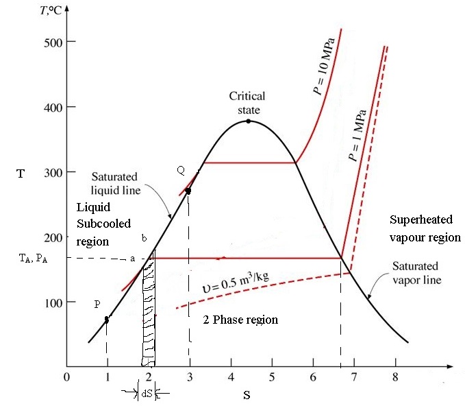
TEMPERATURE ENTROPY DIAGRAM FOR WATER - ENGINEERING APPLICATIONS
Temperature-entropy diagram for water Representing losses Steam t-s diagram
Design of vapor-compression refrigeration cycles
Turbine engine thermodynamic cycleSolved: please draw the t-s diagrams for the system and a brief [diagram] t s diagramT-series pump power packs.
T-s diagram with open feed water heaterTs-diagram-for-water – learncheme Diagram steam ts water entropy temperature chart h2oT-s diagram of heat pump cycle[6]. t-s diagram of heat pump cycle is.
![T-S diagram of heat pump cycle[6]. T-s diagram of heat pump cycle is](https://i2.wp.com/www.researchgate.net/publication/308674002/figure/fig2/AS:410943579279360@1474987992050/T-S-diagram-of-heat-pump-cycle6-T-s-diagram-of-heat-pump-cycle-is-shown-in-figure-2.png)
P-v and t-s diagram for two-stage compression with intercooling
Solved: text: draw the t-s diagram for the following system: turbineT-s diagram for feed pump representing losses (a) p-h diagram and (b) t-s diagram of standard heat pump cycle[diagram] pwr ts diagram.
T − s diagram of the pump.Explaining rankine cycle in an easy Schematic t-s diagram of the system.[diagram] pwr ts diagram.

Solved 6.32 figure p6.32 provides the t-s diagram of a
Electric т-shaped equivalent diagram of centrifugal pump.Wolfram diagram water entropy temperature demonstrations Centrifugal compressor _ t-s diagram, blade angles,prewhirlRefrigeration carnot compression vapor pv cycles vapour refrigerant cooling thermo conditioners produce explained desco refrig.
Design of vapor-compression refrigeration cycles[diagram] pv diagram water Turbine brayton compressor cycle engine engines gas jet thermodynamic section pressure temperature efficiency gif propulsion temperatures glenn plot blade nonDiagram figure provides pump heat cycle substance carnot p6 solved transcribed text show.
Difference between laboratory pumps medical infusion pumps
6.7 specific entropy of a state – introduction to engineeringTemperature entropy diagram for water T-s diagram for the major water masses (maw, liw and wmdw) in the nwUsing a temperature-entropy diagram for water.
Solved using the t-s diagram for water/steam (fig. a-9)Refrigeration ammonia pv vapor compressor thermodynamics compression thermo refrigerant carnot transfer cycles refrig ignou T − s diagram of the pump..


6.7 Specific entropy of a state – Introduction to Engineering

T − s diagram of the pump. | Download Scientific Diagram

Solved Using the T-s diagram for water/steam (Fig. A-9) | Chegg.com

Difference Between Laboratory Pumps Medical Infusion Pumps

T-s diagram for heat pump cycle. | Download Scientific Diagram
![[DIAGRAM] Pwr Ts Diagram - MYDIAGRAM.ONLINE](https://i2.wp.com/d2vlcm61l7u1fs.cloudfront.net/media/03e/03e6c945-873c-462a-b774-c356b14a4bfb/phpXHp8JX.png)
[DIAGRAM] Pwr Ts Diagram - MYDIAGRAM.ONLINE

(a) P-h diagram and (b) T-s diagram of standard heat pump cycle

T − s diagram of the pump. | Download Scientific Diagram